
Circumnavigating pendulum
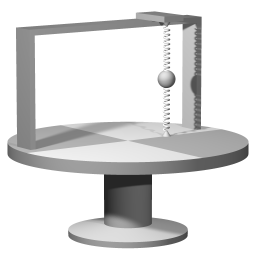
The springs will sustain a vibration of the small sphere. Rotating the platform will affect the vibration.
The subject of this simulation is the motion of a pendulum bob when the attraction point of the pendulum is circumnavigating a central axis.
The simulation explores an abstract, idealized case. The grey dot represents the point of attraction; the red dot experiences a force towards the grey dot. This force is proportional to the distance of the red dot to the grey dot.
I will refer to the force that is represented by the green arrow as 'the elastic force'. The view on the left shows the actual motion of the red dot as it responds to the pull towards the point of attraction. The view on the right shows the motion as seen from a point of view that is co-rotating with the circumnavigation. By clicking on the tabs of the co-rotating view you switch between a close-up and an overview.
Evolution of the simulation
I will first discuss the motion pattern that you see when the simulation plays with the default settings. I will refer to the force that is necessary for sustaining the vibration as 'the restoring force', and I will refer to the force that is necessary for sustaining the circumnavigation as 'the centripetal force'. In this simulation the elastic force provides both the restoring force and the centripetal force. With the default setting the amplitude of the vibration is so small that the restoring force and the centripetal force are comparable in strength.
I will call a swing towards the central axis an 'inward swing' and the swing away from the central axis an 'outward swing'. I will call the swings in the direction that is tangential to the rotation the 'forward swing' and the backward swing.'
The midpoint of the vibration is shifted away from the central axis. The shifted midpoint is an equilibrium point, in the sense that with that amount of shift the elastic force provides the required centripetal force. If there would also be damping the shifted point is where the red dot would come to rest. I will refer to the velocity of co-rotating with the rotating system as 'the equilibrium velocity'.
During an inward swing the centripetal force is doing work (See: conservation of angular momentum). Especially during midswing, when the velocity is largest, the pendulum bob gains on the attraction point, so the motion relative to the co-rotating system turns to the right.
- During an outward swing the centripetal force is doing negative work. Now the pendulum bob experiences loss of angular velocity, causing the pendulum bob to lag behind. Once more the motion relative to the co-rotating system turns to the right.
- During a forward swing the pendulum bob is circumnavigating faster than equillibrium velocity, so it will swing wide; the motion relative to the co-rotating system turns to the right.
- During a backward swing the pendulum bob is circumnavigating slower than equilibrium velocity . Now there is a surplus of centripetal force, pulling the pendulum bob closer to the central axis of rotation.
In all four distinct phases: inward swing, outward swing, forward swing and backward swing, the overall effect arises from the centripetal force and inertia conjointly.
The default setting of the simulation shows a case where the starting amplitude is small compared to the distance to center, but you can explore any combination of those settings.
The Simulation's controls
There are seven input fields: 'Distance to center', 'Starting amplitude', 'Tangent velocity', 'Rotation rate', Vibration rate', 'Close-up size' and 'Close-up shift.
- Distance to center. The distance of the point of attraction to the central axis of rotation.
- Starting amplitude. The initial distance of the particle to the point of attraction.
- Tangent velocity. This is velocity relative to the inertial system. The simulation adjusts this value automatically to effect a release from co-rotating motion. You can change this value, but the change will be undone when for example the button 'Reset view' is used.
- Rotation rate. You are allowed to enter any value, but of course high values are not particularly interesting.
- Vibration rate. You are allowed to enter any value, but with a high vibration rate, such as 10, there are too few calculation steps per vibration cycle, which leads to significant distortion in the calculation.
- Close-up size. The simulation automatically adopts the value that is in the 'Starting amplitude' field, but you can zoom in or zoom out by changing the close-up size.
- Close-up shift. To center the close-up view.
When you start altering a value in an input field the field turns yellow. As long as the field is still yellow the input process is not ready. The input is finalized by pressing the Enter key on the keyboard, and then the field will no longer be yellow.
Purpose of this simulation
Decomposing the elastic force
We have as a law of motion that forces add according to vector addition: when two forces are acting simultaneously the resulting acceleration is the vector sum of the two acceleration vectors. Interestingly, in the case of the circumnavigating pendulum it is helpful to think of the elastic force as decomposed in a centripetal force and a restoring force. Here, 'centripetal force' refers to the required centripetal force to maintain a particle in uniform circumnavigating motion at the System rotation rate.
Check the checkbox 'Decompose' in the simulation. The brown arrow, the restoring force, is calculated by subtracting the required centripetal force (blue arrow) from the elastic force (green arrow).
Acceleration relative to the co-rotating coordinate system
Check the box 'Extra' to open the small window with extra settings. In the presets section, select 'Ellipse'.
Note that when you switch to 'Ellipse' the box 'Lock' is checked. The 'Lock' is for the tangential velocity. Normally that field is updated automatically with every reset, to ensure that the pendulum bob is released from co-rotating motion. When it is locked the tangential velocity is not updated, so you keep the value that you last entered.
'Distance to center'(the distance of the point of attraction to to the origin) has been set to zero, so now the pendulum isn't circumnavigating anymore.
The rotation rate of the coordinate system has been set to the same value as the vibration rate.
With the above settings you get an ellipse-shaped trajectory (or a straight line if you set tangent velocity to zero). The motion relative to the co-rotating coordinate system is then a perfect circle. For every full rotation of the system the red dot goes around the epi-circle twice. Let the rotation rate of the system be called Ω, then the angular velocity of circling the epi-circle is 2Ω. The larger the radius of the epicircle, the larger the velocity (relative to the co-rotating system) of moving along that circle.
Let the velocity relative to the co-rotating sytem be called vcoro, and let the acceleration relative to the co-rotating system be called acoro. Then we have that at all times acoro is at right angles to vcoro, and:
acoro = 2Ωvcoro
This relation applies whenever the moving object is subject to a centripetal force that is exactly proportional to the distance to the central axis of rotation.
The above relation explains the precession of the pendulum swing relative to the co-rotating system. The centripetal force, either doing work or doing negative work, causes an an acceleration acoro at right angles to vcoro.
Calculation strategy
For this simulation I used the following calculation setup: first the motion relative to the inertial coordinate system is calculated, then the results of that calculation are transformed to obtain the motion as seen from a point of view that co-rotates with the rotating system.
Introducing the Foucault pendulum
If you set the 'Distance to center' to zero then the simulation models the motion pattern of a Foucault pendulum that is located precisely on either of the poles. On the poles the central axis of rotation and the point of attraction coincide. Then the trajectory of the pendulum with respect to the inertial coordinate system keeps following the same ellipse (it's an ellipse because the pendulum bob is released from a state of co-rotating with the rotating system. Set the 'Tangent velocity' to zero to get a swing that is a straight line.)
The case of a Foucault pendulum on either of the poles is very straightforward: the trajectory of the pendulum bob in inertial space is stationary, and the Earth is rotating underneath that. Remarkably, the bob of a Foucault pendulum several kilometers away from either of the poles will follow quite a complicated path with respect to the inertial coordinate system, but the shape of the trajectory with respect to the rotating coordinate system will be virtually indistinguishable from the trajectory precisely at the pole.
For the motion pattern of a Foucault pendulum at any latitude between the poles and the equator see the Foucault pendulum simulation
Download options
This simulation has been created with EJS
EJS stores the specifications of a simulation in a plain text file, with extension .xml
You can examine how the simulation has been set up by opening the simulation .xml file with EJS.
Download location for the EJS software
Download location for the circumnavigating pendulum source file
(The file is zipped because a browser will attempt to parse any .xml file.)

This work is licensed under a Creative Commons Attribution-ShareAlike 3.0 Unported License.
Last time this page was modified: June 18 2017