The Sagnac effect
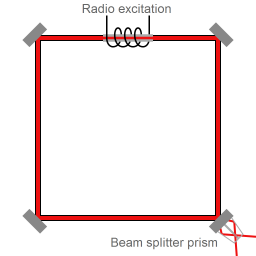
The Sagnac effect manifests itself in an experimental setup called ring interferometry. A beam of light is split and the two beams are made to follow in opposite directions a trajectory that constitutes a ring. To act as a ring the trajectory must enclose an area. The axis of rotation does not have to be inside the enclosed area. The light that exits the ring is guided in such a way that an interference pattern is obtained. The position of the interference fringes is dependent on the angular velocity of the setup. This arrangement is also called a Sagnac interferometer.

Schematic representation of a Sagnac interferometer.
Usually several mirrors are used, so that the lightbeams follow a triangular or square trajectory. Fiber optics can also be employed to guide the light. The ring interferometer is located on a platform that can rotate. When the platform is rotating, the point of entry/exit moves during the transit time of the light, so on exit one beam has covered less distance than the other beam. As a consequence, when the platform is rotating the interference pattern will be shifted as compared to the position of the interference fringes when the platform wasn't rotating. The shift is in proportion to the angular velocity of the Sagnac interferometer.
This type of ring interferometer is sometimes called a 'passive ring interferometer'. A passive ring interferometer uses light entering the setup from outside. The interference pattern that is obtained is a fringe pattern, and what is measured is a phase shift.
Optics and mechanics
The familiar form of rotation sensing is with a mechanical device, using a gimbal mounted gyroscope. It's somewhat unexpected that rotation can also be measured with a purely optical device. Sagnac interferometry suggests that at a deeper level there is a connection between mechanics and optics.
Ring laser
Schematic representation of a ring laser setup. At the beam sampling location a fraction of each of the counterpropagating beams exits the laser cavity.
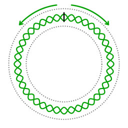
The black line represents a source of waves. The counterpropagating waves give rise to a standing wave.
The wave source has an angular velocity. The counterclockwise propagating wave is shifted to a lower frequency; the clockwise propagating wave is shifted up. The resultant wave has a beat frequency. The envelope of the beat frequency will have no angular velocity. A detector that is co-rotating with the wave source will detect beats in the signal.
It is also possible to construct a ring interferometer that works with light that is generated inside the device itself; an active ring interferometer. The light is generated and sustained by incorporating laser excitation in the ring-shaped path of the light. This setup is called a "ring laser".
Wave mechanics in a ring cavity: general discussion
First I will discuss some general properties of wave mechanics in a ring cavity, and then I will return to the ring laser setup. I will use the following simplification: all the wave energy propagates in a direction parallel to the walls of the ring cavity.
A wave inducing oscillator inside a cavity will induce two counterpropagating waves. By tuning the driving frequency to a resonant frequency a standing wave can be achieved. The wavelength of a standing wave is an integer division of the length of the ring cavity. In other other words, an integer number of wavelengths fits the length of the ring cavity.
In the case depicted in image 4 the oscillation source has an angular velocity. As in case depicted in image 3 the wavelength of each of the counterpropagating waves will be such that an integer number of wavelengths fits into the length of the ring cavity. When the co-propagating wave returns to the oscillation source it has travelled a longer distance than the actual length of the ring cavity. Therefore the resonant frequency will be lower than in the case of a stationary oscillation source. When the counter-propagating wave returns to the oscillation source it has travelled a shorter distance than the actual ring cavity's length. The two counterpropagating waves have a different frequency. Because of the difference in frequency of the two counterpropagating waves there is a beat frequency.
The beat frequency can be thought of as an interference pattern in time, as opposed to the spatial interference pattern that is obtained with a passive Sagnac interferometer. The spatial distribution of the beat frequency can be thought of as a string of beads. A wave energy detector that is co-rotating with the device will travel along the wave pattern, passing the "beads" one by one. The faster the rotation rate of the device, the more "beads" per unit of length of the ring-shaped cavity.
Loop geometry
Essential in the Sagnac effect is that a loop is closed. Because a loop is closed the velocity that is involved is essentially an angular velocity; it's circumnavigation of an area. (If the perimeter of the area is a circle then the angular velocity is constant, but it's not necessary for the the perimeter to be circular. )
Laser process in a ring cavity
As the laser process is started, the atoms or molecules inside the cavity emit photons, but since the molecules have a thermal velocity, the light inside the laser cavity is at first a range of frequencies, corresponding to the statistical distribution of velocities. The process of stimulated emission makes one frequency quickly outcompete other frequencies, and after that the light is extremely close to monochromatic.
Laser is a process of resonance; resonance occurs for a wavelength of the laser light that is an integer division of the length that is travelled by the wave when it returns to the resonator that it started from. Forming a standing wave (or, rather, the quantummechanical counterpart of a standing wave) is inherent to the laser process.
When a ring laser is rotating, the detector will detect a frequency that is consistent with the laser process generating two frequencies of laser light.
Angle between axis of rotation and enclosed area.
It matters whether the area that is circumnavigated by the ring laser cavity is perpendicular to the axis of rotation, or at an angle. The frequency shift is proportional to the projection of the area onto the plane that is perpendicular to the axis of rotation. This projection rule is a sine rule that is reminiscent of the sine rule that applies for the Foucault pendulum. (Interestingly, the swing of a Foucault pendulum can also be thought of as a beat frequency in a superposition of clockwise and counterclockwise motion of a conical pendulum.)
The isotropy of the speed of light acting as background reference
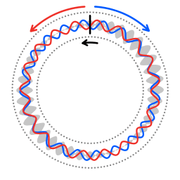
The red and blue dots represent counter-propagating photons, the grey dots represent molecules in the laser cavity.
The beat frequency that is measured by a ring laser interferometer is proportional to the angular velocity of the interferometer setup. That means that for detecting a state of zero angular velocity no separate calibration is required; because of the nature of the process the device self-calibrates. If the detector does not detect a beat frequency then the device isn't rotating.
Of course, any calibration requires a reference. In the case of ring laser interferometry something is providing a reference. Animation 5 illustrates what that reference is. The blue dots and red dots represent counterpropagating photons, the grey dots represent molecules in the laser cavity. For every section along the ring the following is valid: the speed of light is the same in both directions. It has to be the same because the speed of light is the same in all directions. The isotropy of the speed of light constitutes the reference that enables the self-calibration.
Synchronisation procedures
The procedures for synchronizing clocks all over the globe must take the rotation of Earth into account. The signals used for the synchronizing procedure can be in the form of electric pulses conducted in electic wires, they can be lightpulses conducted in fiber optic cables, or they can be radio signals.
If a number of stations, situated on the equator, relay pulses to one another, will the time-keeping still match after the relay has circumnavigated the globe? One condition for handling the relay correctly is that the time it takes the signal to travel from one station to the next is taken into account each time. On a non-rotating planet that ensures fidelity: two time-disseminating relays, going full circle in opposite directions around the globe, will still match when they are compared at the end. However, on a rotating planet, it must also be taken into account that the receiver circumnavigates an enclosed area during the transit time of the signal, shortening or lengthening the transit time compared to what it would be in the situation of a non-rotating planet.
Loop geometry
It is recognized that the synchronisation of clocks and ring interferometry are related in a fundamental way. Therefore the necessity to take the rotation of Earth into account in synchronisation procedures for a setup with a loop geometry is also called the Sagnac effect.
Practical applications of the Sagnac Effect
The Sagnac Effect is employed in current technology. One use is in Inertial guidance systems. Ring interferometers are extremely sensitive to rotations, which need to be accounted for if an inertial guidance system is to return correct results.
The Global Positioning System needs to take the rotation of Earth into account in the procedures of using radio signals to synchronize clocks.
History
The first to perform this type of interferometric experiment was the Frenchman G. Sagnac in 1913, which is why the effect is named after him. The purpose of the experiment was to detect "the effect of the relative motion of the ether". An experiment conducted in 1911 by F. Harress, aimed at making measurements of Fresnel drag of light propagating through moving glass, was later recognized as actually constituting a Sagnac experiment. Harress had ascribed the "unexpected bias" to something else.
In 1926 a very ambitious ring interferometry experiment was set up by Michelson and Gale. The aim was to find out whether the rotation of Earth has an effect on the propagation of light in the vicinity of Earth. The Michelson-Gale experiment was a very large ring interferometer, (a perimeter of 1.9 kilometer), large enough to detect the angular velocity of Earth. The outcome of the experiment was that the angular velocity of Earth as measured by astronomy was confirmed to within measuring accuracy. The ring interferometer of the Michelson-Gale experiment was not calibrated by comparison with an outside reference (which was not possible, because the setup was fixed to the Earth). From its design it could be deduced where the central interference fringe ought to be if there would be zero shift. The measured shift was 230 parts in 1000, with an accuracy of 5 parts in 1000. The predicted shift was 237 parts in 1000.
The Michelson-Gale experiment had no scientific impact, but it is technically very interesting. Astronomers measure the Earth's rotation by tracking stars, that is: measurement of rotation with respect to other celestial bodies. The novelty of the Michelson-Gale experiment was that it measured the rotation of the Earth with respect to space. The experiment did not involve reference to other celestial bodies: not for the measurement itself and not for calibration of the instrument.
Foucault's 1852 gyroscope was the first gyroscope that was manufactured with sufficient accuracy to measure the Earth's rotation. (Even a minute imbalance of the gyroscope gives rise to spurious results.) The Foucault gyroscope was the first instrument to offer a way to measure the Earth's rotation relative to space using only local observation. The 1926 Michelson-Gale Sagnac interferometer experiment was the first optical measurement of the Earth's rotation with respect to space.
Resources
G. Sagnac, Comptes Rendus de l'Academie des Sciences (Paris) 157, pp.708-710,1410-1413 (1913)
Large Laser Gyroscopes for Monitoring Earth Rotation
Mathpages.com article on the Sagnac Effect
The Sagnac Effect and its Application for GPS GPS-related article by Neil Ashby
Major parts of this article have been uploaded by me to the wikipedia article about the Sagnac effect.
Wikipeda text is available under the terms of the GNU Free Documentation License

This work is licensed under a Creative Commons Attribution-ShareAlike 3.0 Unported License.
Last time this page was modified: June 18 2017